- 您现在的位置:买卖IC网 > Sheet目录474 > MAX66000K-000AA+ (Maxim Integrated)IC RFID UID 64BIT TYPE B KEY FOB
ISO/IEC 14443 Type B-Compliant
64-Bit UID
ABSOLUTE MAXIMUM RATINGS
Maximum Incident Magnetic Field Strength ..........141.5dBμA/m
Operating Temperature Range ...........................-25°C to +50°C
Relative Humidity ..............................................(Water Resistant)
Storage Temperature Range ...............................-25°C to +50°C
Stresses beyond those listed under “Absolute Maximum Ratings” may cause permanent damage to the device. These are stress ratings only, and functional
operation of the device at these or any other conditions beyond those indicated in the operational sections of the specifications is not implied. Exposure to
absolute maximum rating conditions for extended periods may affect device reliability.
ELECTRICAL CHARACTERISTICS
(T A = -25°C to +50°C.) (Note 1)
PARAMETER
SYMBOL
CONDITIONS
MIN
TYP
MAX
UNITS
RF INTERFACE
Carrier Frequency
Operating Magnetic Field Strength
(Note 1)
Power-Up Time
f C
H
t POR
(Note 1)
At +25°C, MAX66000E
At +25°C, MAX66000K
(Note 2)
13.553
111.0
123.5
13.560
13.567
137.5
137.5
1.0
MHz
dBμA/m
ms
Note 1: System requirement.
Note 2: Measured from the time at which the incident field is present with strength greater than or equal to H (MIN) to the time at
which the MAX66000’s internal power-on reset signal is deasserted and the device is ready to receive a command frame.
Not characterized or production tested; guaranteed by simulation only.
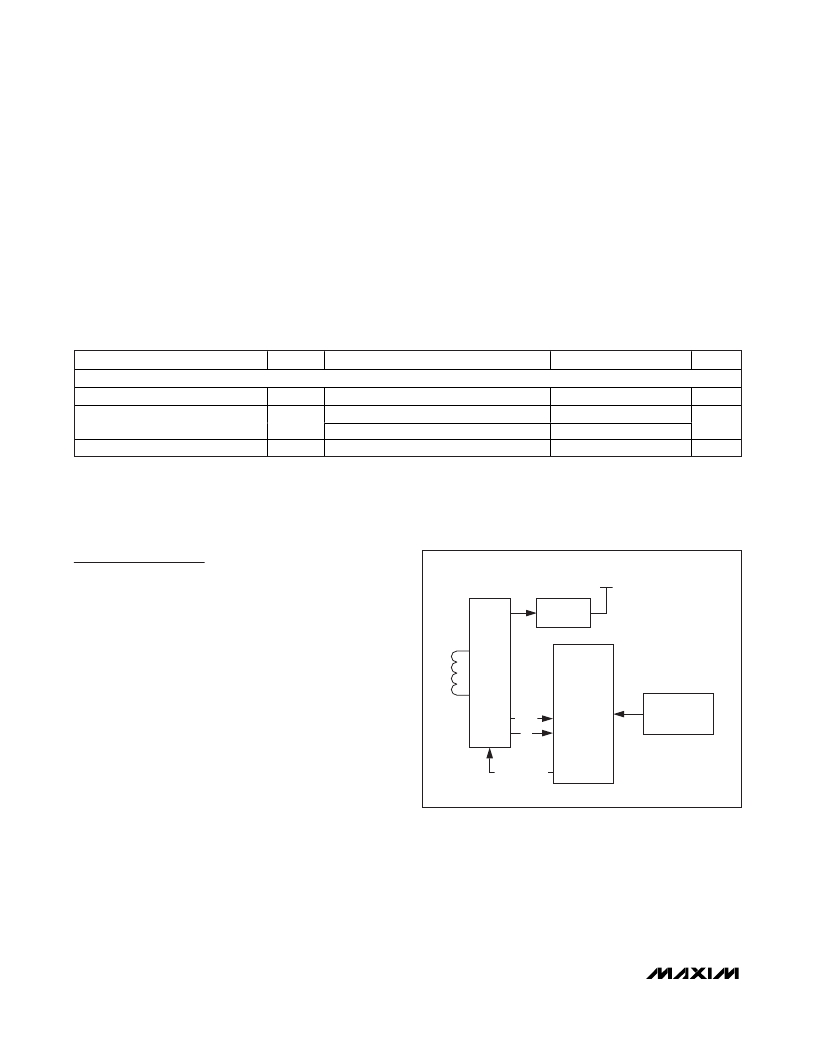
Detailed Description
The MAX66000 combines a 64-bit UID and a
13.56MHz RF interface (ISO/IEC 14443 Type B, Parts
2-4) in a single chip. The UID can be read through the
ISO/IEC 14443-4 block transmission protocol, where
requests and responses are exchanged through I-
blocks once a device is in the ACTIVE state. The read-
INTERNALSUPPLY
VOLTAGE
REGULATOR
er must support a frame size of at least 19 bytes. The
data rate can be as high as 847.5kbps. The MAX66000
supports AFI and CID. ISO 14443 functions not sup-
RF
FRONT-
END
ISO 14443
ported are chaining, frame-waiting time extension, and
power indication. Applications of the MAX66000
include driver identification (fleet application), access
DATA
f c
FRAME
FORMATTING
AND
ERROR
UID, AFI,
APPLICATION
DATA FIELD
control, and asset tracking.
Overview
Figure 1 shows the relationships between the major
control and memory sections of the MAX66000.
Figure 2 shows the hierarchical structure of the ISO/IEC
14443 Type B-compliant access protocol. The master
must first apply network function commands to put the
MAX66000 into the ACTIVE state to read the UID or
system information. The protocol required for these net-
work function commands is described in the Network
Function Commands section. Once the MAX66000 is in
the ACTIVE state, the master can use the memory func-
tion commands. Upon completion of such a command,
DETECTION
MODULATION
Figure 1. Block Diagram
the MAX66000 returns to the ACTIVE state and the
master can issue another memory function command or
deselect the device, which returns it to the HALT state.
The protocol for these commands is described in the
Memory Commands section. All data is read and writ-
ten least significant bit (LSb) first, starting with the least
significant byte (LSB).
2
_______________________________________________________________________________________
发布紧急采购,3分钟左右您将得到回复。
相关PDF资料
MAX66020K-000AA+
IC RFID UID 1KB TYPEB MEM KEYFOB
MAX66040K-000AA+
ISO CARD SECURE MEMORY
MAX6605MXK/V+T
IC TEMP SENSOR ANLG LP SC70-5
MAX6608IUK+T
IC TEMP SENSOR ANLG SOT23-5
MAX66100K-000AA+
IC RFID UID 64BIT TYPE B KEY FOB
MAX6611AUT+T
IC TEMP SENS LOW PWR SOT23-6
MAX66120K-000AA+
IC RFID UID 1KB TYPEB MEM KEYFOB
MAX6612MXK+T
IC TEMP SENSOR ANLG SC70-5
相关代理商/技术参数
MAX66000K-00AA+
制造商:Maxim Integrated Products 功能描述:ISO/IEC 14443 TYPE B-COMPLIANT 64-BIT, UID FOB - Rail/Tube
MAX66020K-000AA+
功能描述:RFID应答器 ISO/IEC 14443 Type B Comp 1Kb Mem Fob
RoHS:否 制造商:Murata 存储容量:512 bit 工作温度范围:- 40 C to + 85 C 安装风格:SMD/SMT 封装 / 箱体: 封装:Reel
MAX66020K-00AA+
制造商:Maxim Integrated Products 功能描述:ISO/IEC 14443 TYPE B-COMPLIANT 1KB MEMORY FOB - Rail/Tube
MAX6602UE9A+
功能描述:板上安装温度传感器 5Ch Precision Temperature Monitor RoHS:否 制造商:Omron Electronics 输出类型:Digital 配置: 准确性:+/- 1.5 C, +/- 3 C 温度阈值: 数字输出 - 总线接口:2-Wire, I2C, SMBus 电源电压-最大:5.5 V 电源电压-最小:4.5 V 最大工作温度:+ 50 C 最小工作温度:0 C 关闭: 安装风格: 封装 / 箱体: 设备功能:Temperature and Humidity Sensor
MAX6602UE9A+T
功能描述:板上安装温度传感器 5Ch Precision Temperature Monitor RoHS:否 制造商:Omron Electronics 输出类型:Digital 配置: 准确性:+/- 1.5 C, +/- 3 C 温度阈值: 数字输出 - 总线接口:2-Wire, I2C, SMBus 电源电压-最大:5.5 V 电源电压-最小:4.5 V 最大工作温度:+ 50 C 最小工作温度:0 C 关闭: 安装风格: 封装 / 箱体: 设备功能:Temperature and Humidity Sensor
MAX6603ATB
制造商:Maxim Integrated Products 功能描述:DUAL-CHANNEL PLATINUM RTD-TO-VOLTAG - Rail/Tube
MAX6603ATB+
制造商:Maxim Integrated Products 功能描述:RTD TO VOLT SGNL CONDITIONER 10TDFN EP - Rail/Tube
MAX6603ATB+T
功能描述:板上安装温度传感器 RTD-to-Voltage Signal Conditioner RoHS:否 制造商:Omron Electronics 输出类型:Digital 配置: 准确性:+/- 1.5 C, +/- 3 C 温度阈值: 数字输出 - 总线接口:2-Wire, I2C, SMBus 电源电压-最大:5.5 V 电源电压-最小:4.5 V 最大工作温度:+ 50 C 最小工作温度:0 C 关闭: 安装风格: 封装 / 箱体: 设备功能:Temperature and Humidity Sensor
